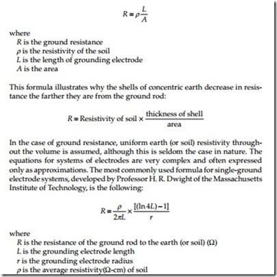
Ground Rod Resistance Formula
Electrical Power System Grounding And Ground Resistance Measurements Understanding Ground Resistance Electrical Power Generation

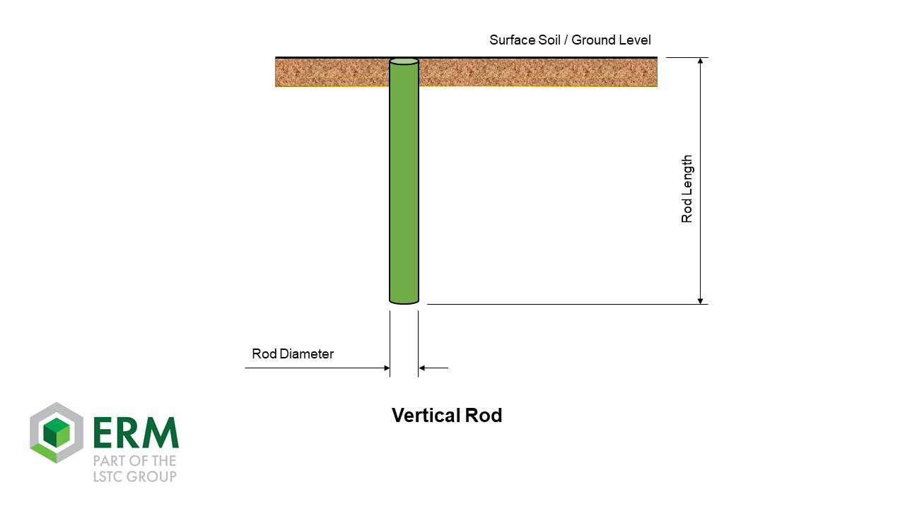
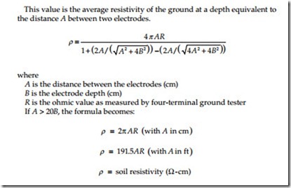
How To Calculate The Apparent Resistivity In The Cases Of Horizontal And Vertical Electrodes

Measurements And Calculations Of Earth Electrode Systems Bs 7430 Eep
Calculating Ground Electrode Resistance Of A Single Rod Ground Electrode Design Principles And Testing Nvent

Basics Of Ground Rod Testing Ppt Video Online Download

Understanding Soil Resistivity Testing Shopaemc Com
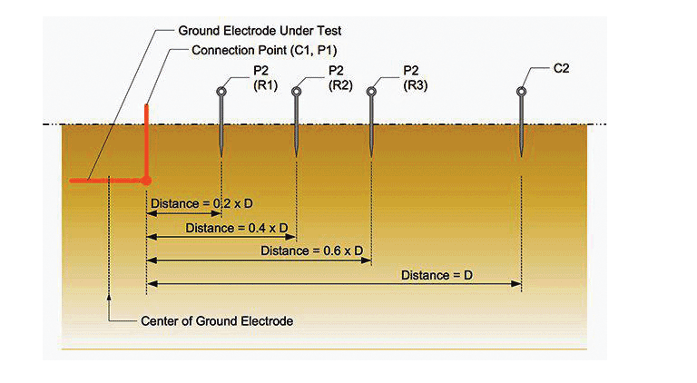
P2 and c2 connect to a separate all metallic grounding point like a water pipe or building steel.
Ground rod resistance formula.
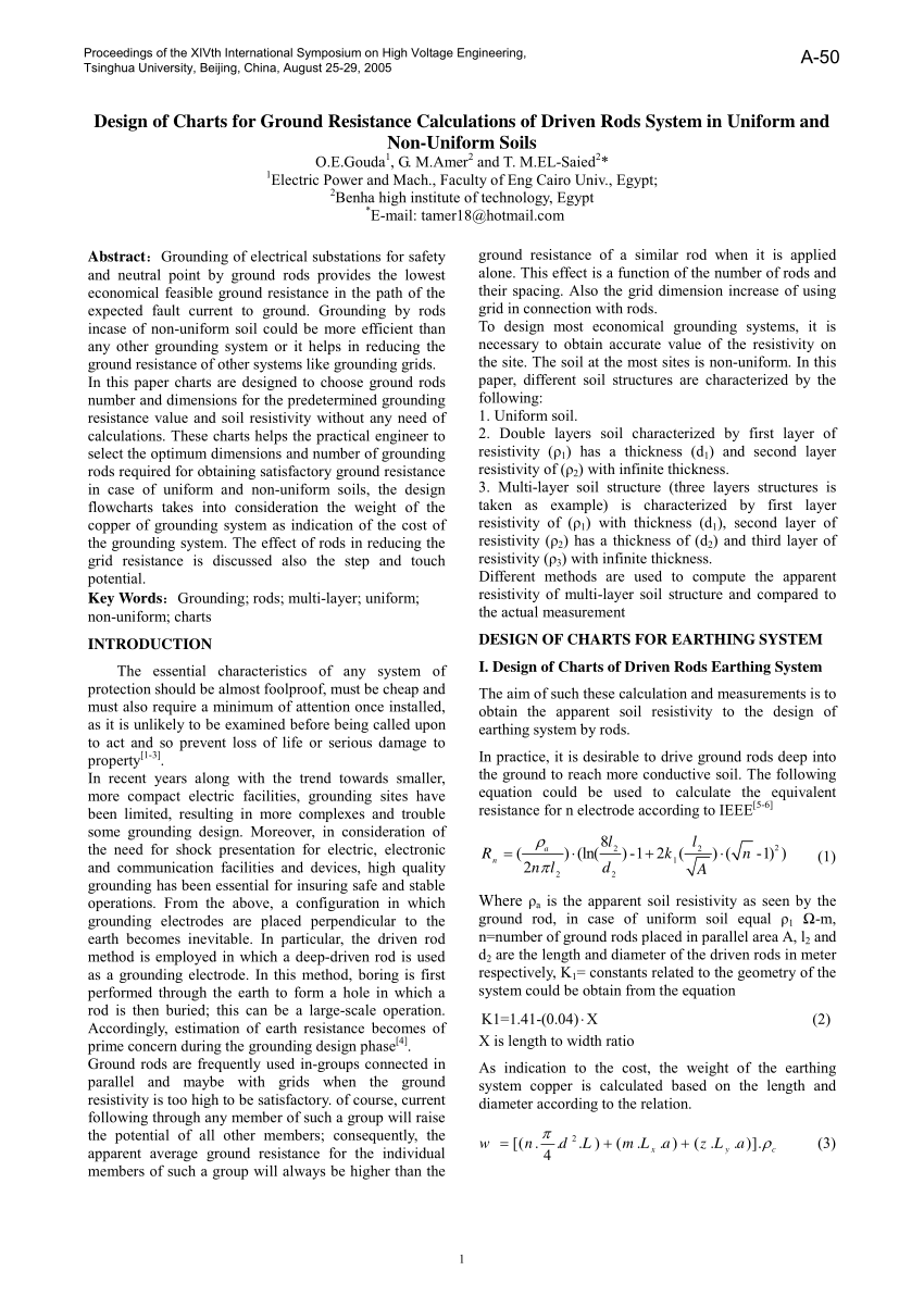
Pdf Design Of Charts For Ground Resistance Calculations Of Driven Rods System In Uniform And Non Uniform Soils

Earth Electrode Testing Youtube

Understanding Soil Resistivity Testing Utility Products
Earthing Resistance And Measurement Practices Electrical Power Review Case Study

How To Get A Grounding Rod Below 1ohm Ground Resistance E S Grounding Solutions
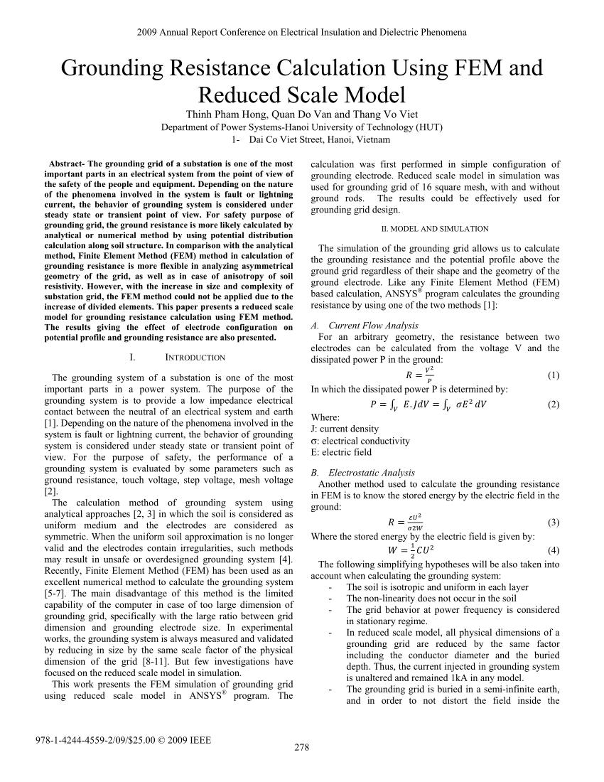
Pdf Grounding Resistance Calculation Using Fem And Reduced Scale Model
Electrical Test Equipment Power Station To Plug Megger
Https Encrypted Tbn0 Gstatic Com Images Q Tbn 3aand9gct73trml62roenqjh89mifsaed1jqcgmr51rg Usqp Cau

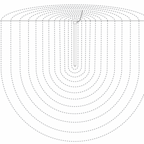
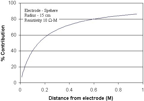
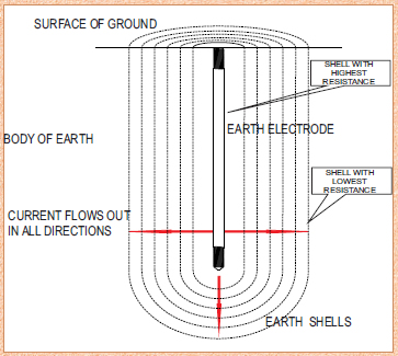
Grounding Electrode Sphere Of Influence E S Grounding

Earthing Grounding System According To Iec Bs En And Ieee Standards Cbm Technology
Calculation Tools Erm
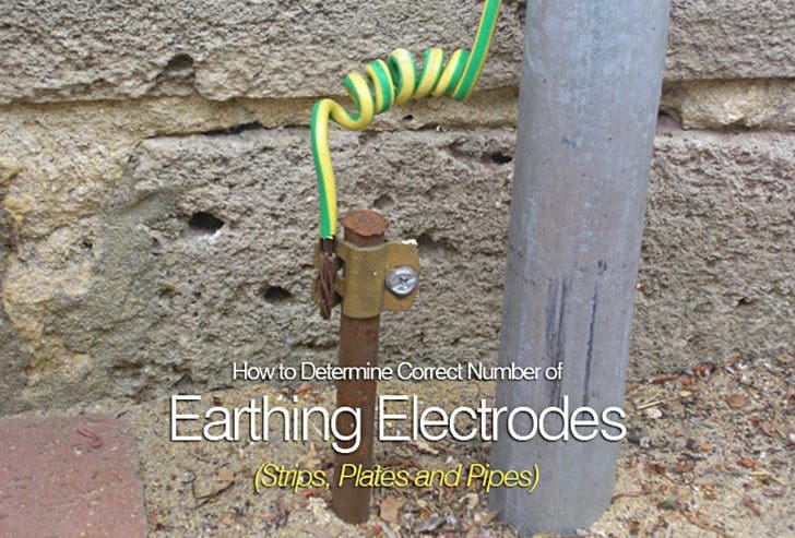
How To Determine Correct Number Of Earthing Electrodes Strips Plates And Pipes Part 1
Earth Electrode Resistance
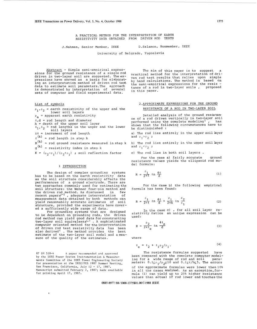
Pdf Practical Method For The Interpretation Of Earth Resistivity Data Obtained From Driven Rod Tests

Principles And Testing Methods Of Earth Ground Resistance Ee Publishers

Pdf Resistance To Ground Of Combined Grid Multiple Rods Electrodes
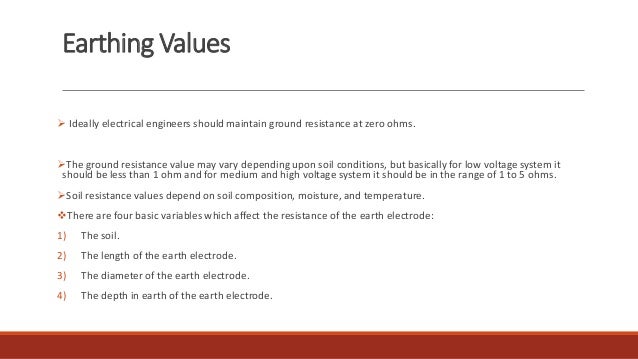
Electrode Resistance Earthing Requirements Lectro Tech
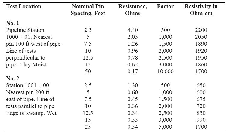
Electrical Power System Grounding And Ground Resistance Measurements Soil Resistivity Measurements Four Point Measurement Electrical Power Generation
Https Encrypted Tbn0 Gstatic Com Images Q Tbn 3aand9gcsuq8ijormmpvmlm4gomwgiio9o9mvpyusbackoljgjz Xjlarg Usqp Cau

What Is Soil Resistivity Testing E S Grounding Solutions

Methods Of Earth Resistance Testing Part 1 Electrical Notes Articles
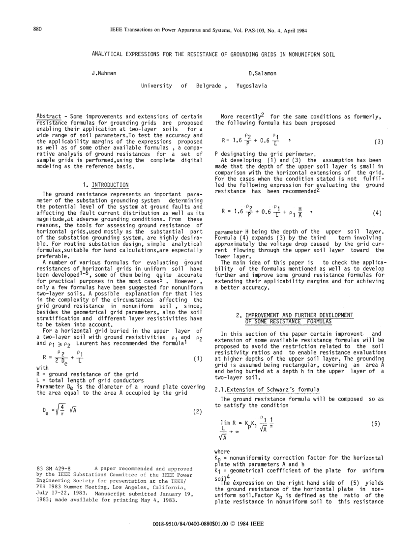
Pdf Analytical Expressions For The Resistance Of Grounding Grids In Nonuniform Soil
Earth Resistance Calculation
Ground System Resistance Vs Impedance Alltec Lightning Protection Surge Suppression Grounding Solutions
Source : pinterest.com
